
New to this machine? Start with our complete G0704 resource page — specs, quirks, and the full upgrade path.
This is the complete installation guide for the G0704 Ultimate Spindle Upgrade Kit — belt drive, power drawbar, and precision spindle. Prefer paper? Download the PDF version. Stuck on a step? Reach out — helping customers through installs is what we do.
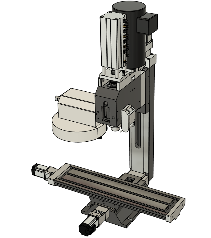
Preparations
Layout your hardware bags along with your kit components and match up each bag with its associated components, this will make following along with the manual much easier.
Recommended Optional Upgrades for best performance and use:
Optional Upgrade 1
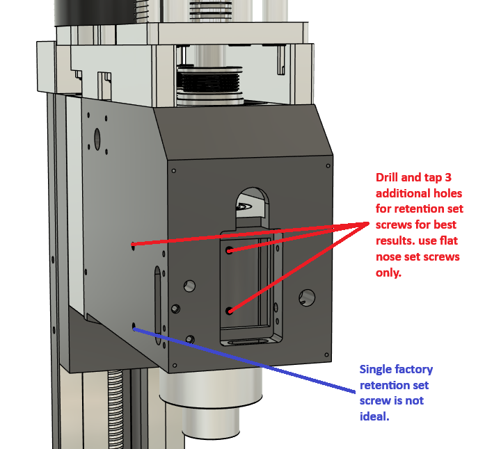
Add Additional support set screws to better spread the load in holding the spindle in the headstock casting these can be M8x1.25 set screws with a flat nose only. Drill and tap in the approximate location ensuring the tapped holes are on the centerline of the spindle axis.
Optional Upgrade 2
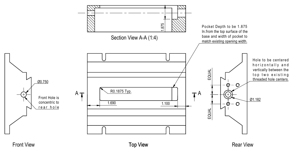
Preparation for extended Y travels. If you plan to extend the Y travels on your machine, you will want to modify the base accordingly. Below is the drawing for modifying the base to accommodate the maximum travels with this kit offering you ~ 9.5” of travel with the appropriate length ballscrew and repositioned screw axis centerline.
Main Kit Installation
Step 1
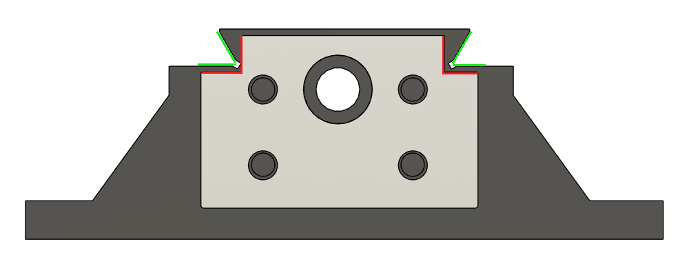
Base and column spacer is installed. Carefully note the direction of installation. Compare the two notches on the top side edges, these are for clearance of the Y axis saddle dovetail corners as it over travels towards the rear of the machine. Be sure when installed that the notches are on the correct sides, the saddle is NOT symmetrical in this regard, nor is the spacer.
Step 2
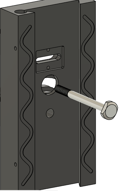
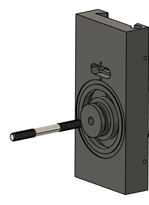
Install the three T-bolts in the Z saddle. The backside of the saddle has a passthrough hole for the heads to fit through, all three need to be installed and can just rest at the bottom of the swivel pocket. Install the 12mm swivel stud in the z saddle making sure the threads do not go beyond the back side of the saddle casting. reinstall the z saddle to the column and connect your z axis ballscrew assembly and adjust your Z axis saddle Gibs.
Preparation
for tramming: At this stage of assembly it is a good idea to tram the column before all of the added weight of the head assembly is installed which makes tramming much more difficult. First things first, ensure that the X, Y and Z axes gib adjustments are correctly set and that motion of all 3 axis is smooth and tight without play nor binding. Having these adjustment correct ensures the machine is in its proper state of affairs before we begin adjusting Items that build upon those correctly adjusted gibs.
Tram Step 1
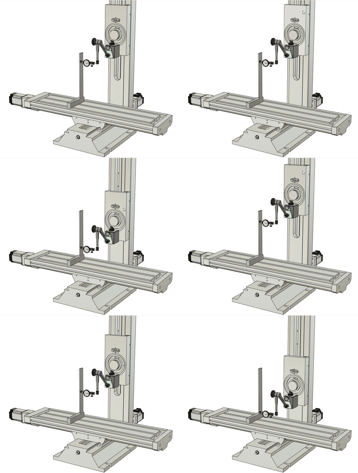
Tramming the column for front to back tilt. This is ALWAYS the first tram adjustment you should make, each step builds upon the last from this point so if you get things wrong here the tolerance deviations will begin to stack. This step ensures the head moves perpendicular to the Y axis when traveling along the z axis. This adjustment requires shimming the column at the top or bottom of the column spacer between the base and column until you are within your desired machining tolerance deviation. This adjustment is measured by running the head up and down the z axis while testing against a precision square setup on the table and an indicator on the Z saddle. You are looking for the change in indicator reading to be under 0.001” per 6” of z travel. On a machine of this size 0.001” per 6” of travel is fairly good, it can be made better but that is not too bad at all. Always finish tramming front to back tilt before tramming for side-to-side tilt.
Tram Step 2
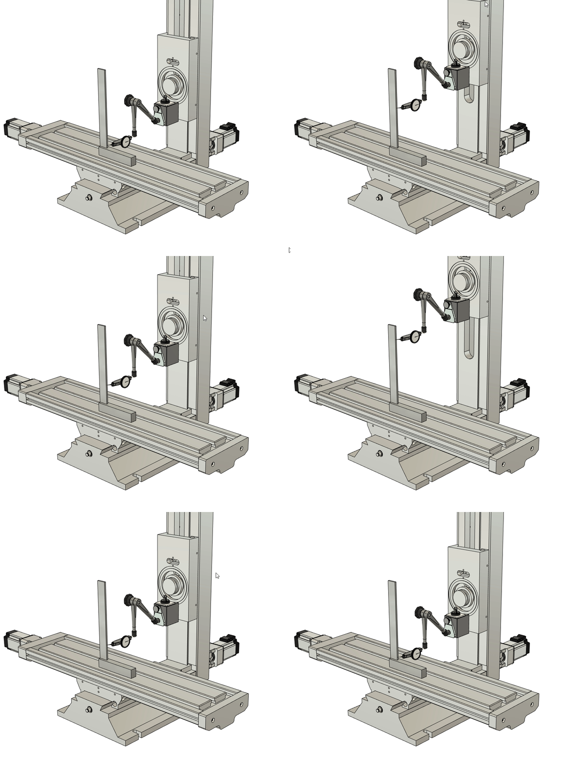
Tramming the column for side-to-side tilt. This ensures that the head travels perpendicular to X axis while moving along the Z axis. This adjustment is made by slightly breaking loose the column bolts that fasten into the base and gently tapping the column into tram while testing against a precision square setup on the table and an indicator on the Z saddle. Run the z axis up and down until indicator deviation is under 0.001” per 6” of z travel. Again you can take more time here if perfection is your goal but it is very difficult obtaining better than those figures from experience ( not that it has stopped me from striving for better… 😊). With the Column Trammed you can proceed with assembly Step 3!
Step 3
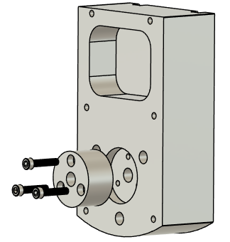
Install the aluminum swivel puck with the 3 supplied M6 cap screws into the large aluminum head spacer.
Step 4
Insert the head spacer onto the back of the head and align it to the head. I recommend marking one hole location first to hold things in place while marking the other five hole locations. Using a 15/64" transfer punch or drill bit you will mark hole location on the back of the head casting. The drilled and tapped holes are for the supplied M5 x0.8 fasteners. Using a #18 (0.1695”) drill bit to drill 0.50” deep pilot hole and tap the hole for fully formed threads a minimum of 0.40” deep. Ensure that your tap creates threads to this depth to ensure the fasteners do not bottom out before reaching clamping depth. Now reinstall the head spacer to the head and install the M5 fastener to help hold everything aligned while you mark the other 5 holes with the transfer punch. Once marked, drill and tap the remaining 5 holes. Install the head spacer and all six M5 bolts using non-permanent Loctite blue or similar through the spacer into the head casting.
Step 5
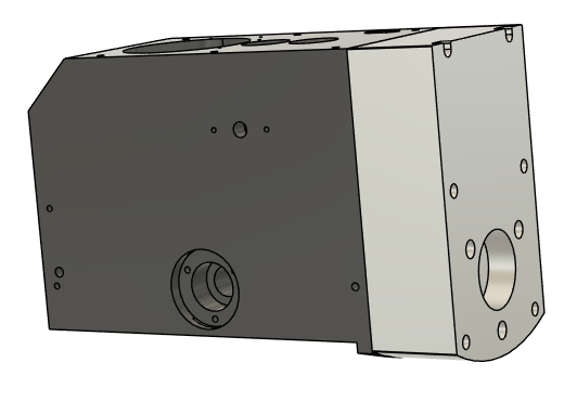
(Read entire step before proceeding) Install the spindle pulley assembly into the top of the head. the fit with a clean set of bearing bores in the head casting should NOT be too terribly tight and some very light taps with a plastic dead blow around the outer edge of the bearing with a flat block of aluminum should suffice being careful to walk around the bearings outer edge to maintain straight force while tapping it in. A press can also be used but do not press on the drive tube, only the outer bearing races edges! Be sure the lower bearing fully seats in its pocket. There will be a small gap between the top of the head casting and the edge of the bearing where it sits slightly recessed. This varies from machine to machine so there is not an exact measurement. ideally you can measure the top of the head to the lower bearing pocket floor and compare it to the height of the two bearings on the drive tube to get your exact distance to check for.
Step 6
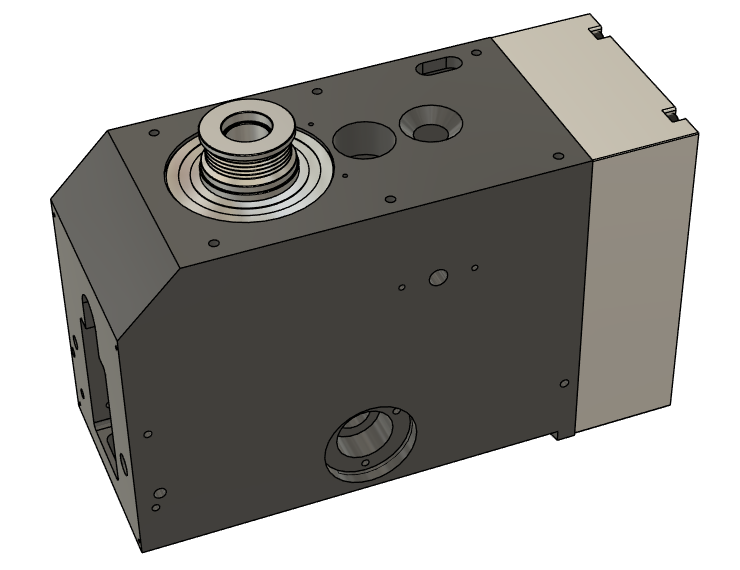
install the head casting with spacer onto the Z axis Saddle, you will need to align the t bolts for the holes through the head spacer and head 120 degrees apart. It is most easily done with the head on the table with Y forward enough to move the table with the head onto the z saddle this way you aren't trying to suspend the weight yourself. You can lay the head on its side with a block of wood so you have access to the underside where the nuts and washers for the T-bolts and stud will be installed. Leave the nuts just loose enough to swivel the head without the force being applied to the puck alone once you raise it off the wood block. swivel the head into normal position and snug the nuts once in position.
Step 7
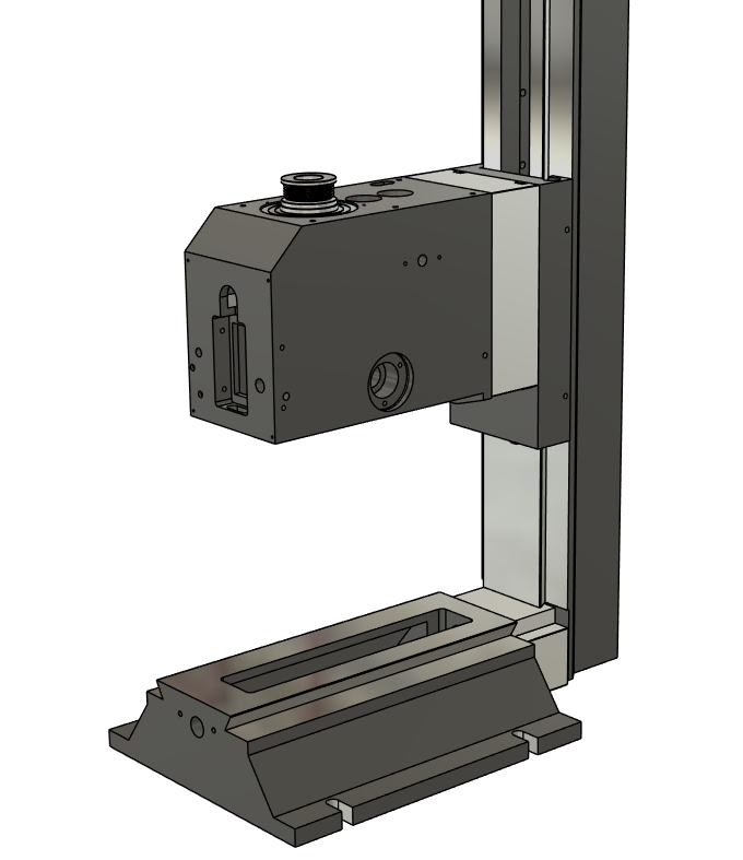
Reinstall the spindle cartridge. If there was a factory O-ring between the bottom of the spindle cartridge and the head casting to soften the return contact of the quill on your machine, remove it, it is NOT used for cnc or with this kit. secure the locking set screw on the left side of the head that holds the spindle cartridge in place.
Step 8
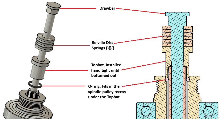
Install the tophat from the drawbar assembly along with the supplied o-ring (will sandwich into the recess of the top of the spindle pulley and the bottom of the tophat, this quiets any spline rattle while running). check the runout of the top hat on your spindle, it should be less than 0.005" (less is better) around the top outer edge. If it is not, your threads on the spindle top may have burrs that should be addressed. This will be the pedestal for the spring discs, and we want those to spin as true as possible to avoid vibrations in the spindle when at high speed.
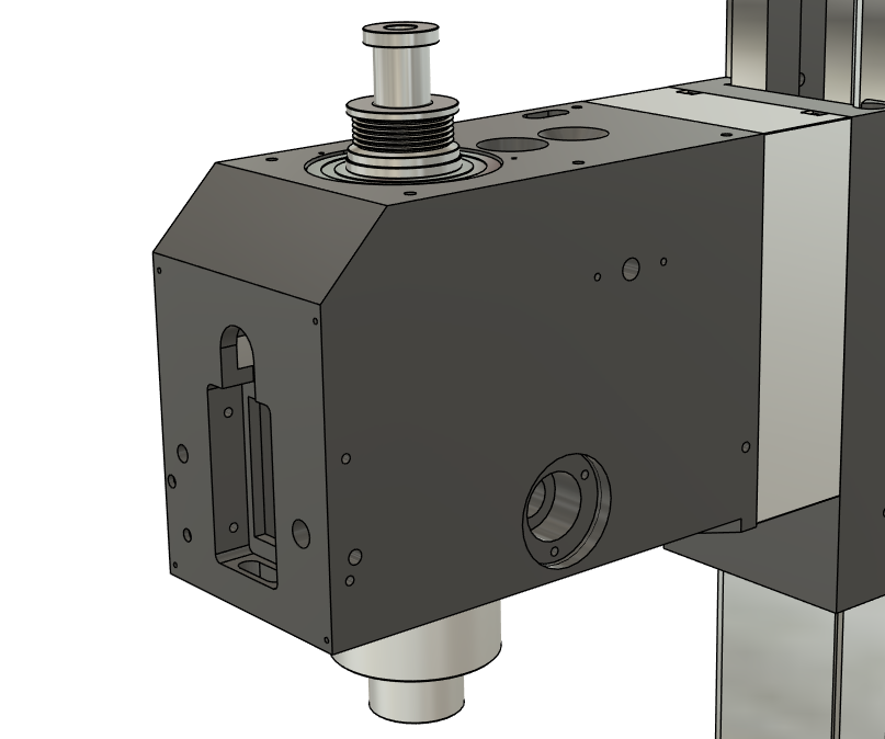
Step 9
Install the two motor stands onto the top of the head casting with the 6 supplied fasteners. leave the fastener just loose enough to move the motor stands around a little bit.
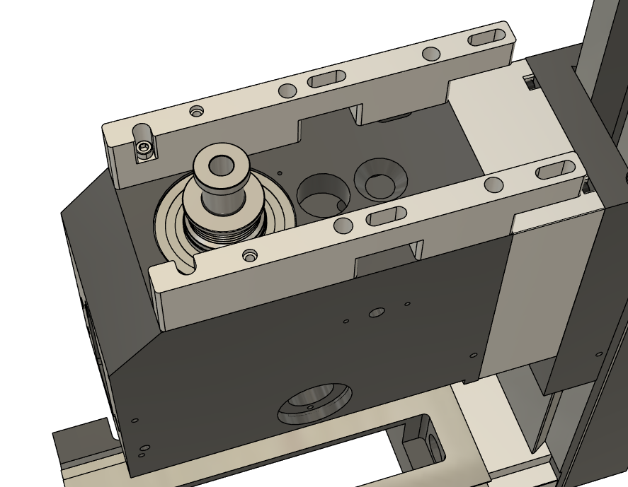
Step 10
Install the four M8 studs into the motor plate on the bottom side (side without the recess for the motor faceplate boss). Now with the motor plate front (the side where studs are closest to the edge of the plate) facing towards the front of the head, set into the motor stand slots. Adjustment may be needed here to give the correct alignment and sliding fit in the motor stand which is why the fasteners were left a little loose in the previous step. Go to step 11 and do not tighten anything yet.
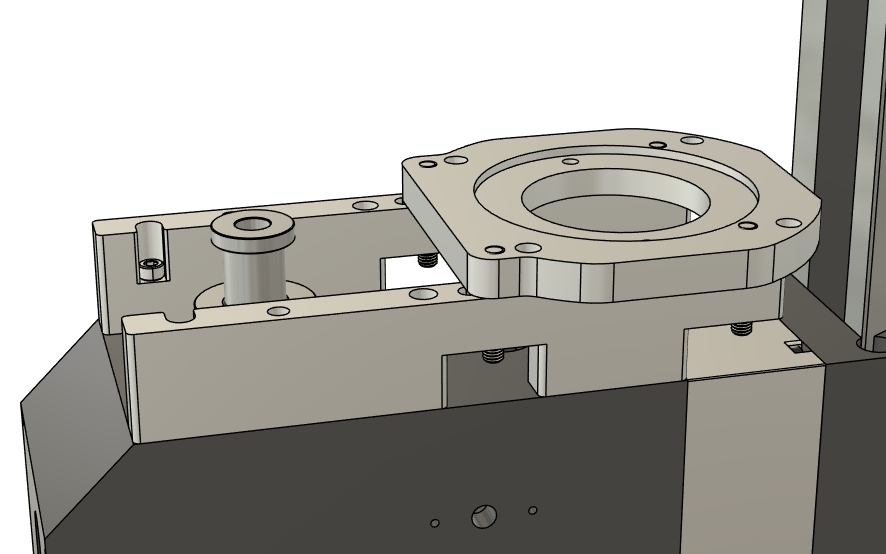
Step 11
Remove the springs from the 2 shoulder bolts supplied for the base of the power drawbar lift plate. Set the lift plate on the front of the motor stands with the machined slot opening in the center facing the back of the machine. Install the two shoulder bolts through the two holes on each side and into the threaded holes in the top of the motor stands. This will also be an alignment step. Once the shoulder bolts are gently snugged up, the primary alignment will be the PDB Lift plate slot and the spindle tophat. We want to make sure there is NO contact here as the spindle rotates. Adjust the alignment of the motor stands so that the tophat is centered in the liftplate’s slot half circle. Once that is adjusted, then check the lift plate’s vertical sliding on the shoulder bolts until it makes contact with the tophat. Make sure it can move somewhat freely; a little drag is acceptable and expected from machine to machine, but heavy binding is not ok. Once the fit feels ok, snug the two center M6 cap screws in the motor stands to hold the position. Next find the two holes in the recess of the motor plate, slide the motor plate until you can see the M6 fastener heads in the motor stands underneath the motor plate and snug them up. Recheck all alignments from above, re-adjust as necessary until all fitment is correct. Now tighten the 4 motor stand screws that are accessible from above. Now remove the shoulder screws and the lift plate and tighten the two front M6 cap screws. Reinstall the lift plate and shoulder bolts and double check alignment once more now with all motor stand fasteners tightened down. Remove the lift plate and motor plate from the motor stands for more assembly steps.
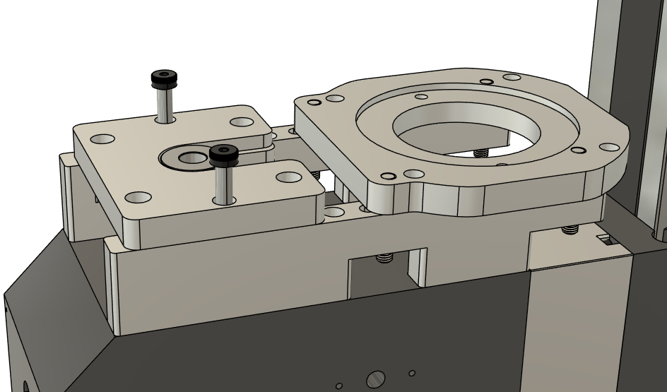
Step 12
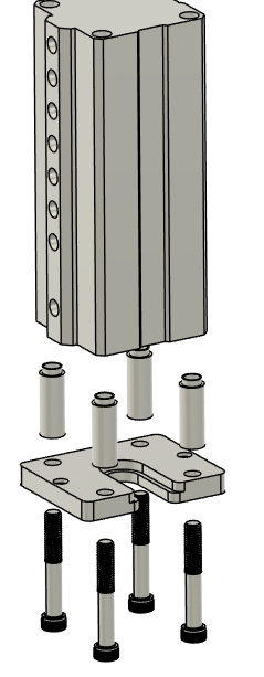
Assemble the Power Drawbar Air Cylinder, Lift plate and Legs as shown. You can position the air cylinder to suit your build with the airline fitting side on either side of the machine. They will NOT fit facing rearward as the motor occupies this space. The slot opening of the lift plate faces the motor side.
Step 13
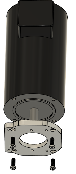
Assemble the motor to the motor plate. Using the four 3/8-16 low profile socket head cap screws, assembly the motor to the motor plate, the extended geometry of the motor plate faces towards the front. The motor wiring compartment must be on the left or right side and cannot face the front or the rear.
Step 14
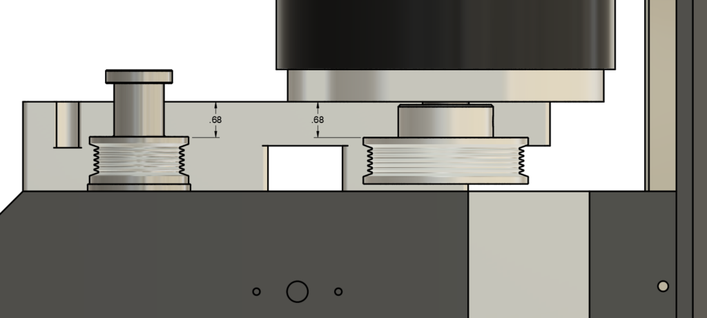
Install the motor pulley. Install the keyway to the motor shaft and loosen the set screw on the upper boss of the motor pulley to ensure it slips onto the motor shaft without interfering. The pulley to motor shaft fit is tight intentionally to avoid any unnecessary runout in the drive system. Setting the motor pulley height to be parallel to the spindle pulley requires taking measurements. lay a parallel across the two motor stands and measure down to the top of the spindle pulley, record the measurement and subtract the parallel thickness and record that height. This height will be the distance from the top of the large motor pulley face to the underside of the motor plate to have correct belt parallelism between pulleys and offer the smoothest quietest operation.
💡 Pro tip: With the motor shaft facing up, set up gage blocks (or make a block or machinist jack) with the previously recorded height. Set the gage block on the motor plate near the round opening so that the face of the pulley will intersect the top of the gage block when installed. This will be used as a stop to set the correct installed height. Use a heat gun to heat the pulley. Wearing insulated gloves to protect yourself from burns, align the pulley keyway to the motor shaft key and slide the pulley over the spindle shaft. The pulley should slide on and stop on the gage block ensuring perfect alignment height. Let cool and tighten the set screw using Loctite blue or similar non-permanent locking compound for the set screw threads.
Step 15
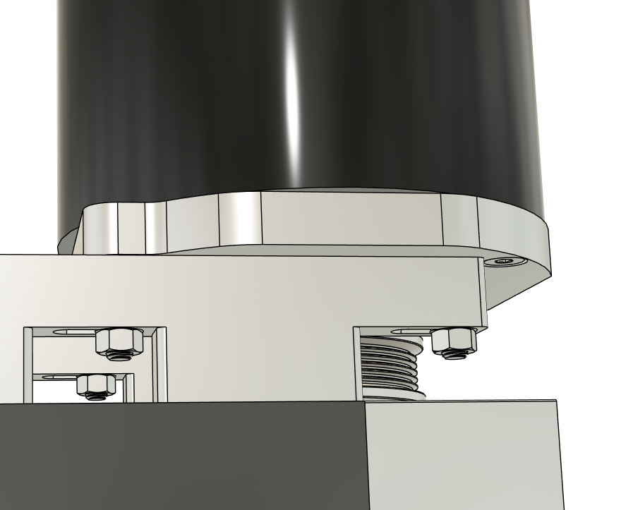
Install the motor on the mill head. Important: install the belt around the spindle pulley and pull back around the motor pulley area before lowering the motor onto the head as it cannot be installed around the motor pulley once the motor is in place. This may require a spare set of helping hands to avoid frustration while handling the very heavy motor assembly. You should still have the four M8 Studs installed on the motor plate from the earlier alignment step. You can simply lower the motor carefully onto the motor stands guiding the studs into the adjustment slots in the motor stands. Use the supplied M8 flange nuts to lightly secure the motor to the stands. Ensure the belt is correctly positioned on both pulleys and slide to the motor towards the back of the head to tension the belt, do not worry about making the belt perfectly tight as we will handle that during break-in procedure later.
Step 16
Spindle Bearing Break-in Procedure. While we are certain you are wanting to play with the drawbar, it is first necessary to break in the spindle bearings and this involves potentially removing the spindle from the head for adjusting the bearing preload which is done with the entire drawbar assembly removed. So we recommend taking the time to complete the other wiring for the motor and getting the spindle operational to perform the break in procedure before continuing with the remainder of the drawbar installation.
Whether you purchased Precision Nachi Bearings from us or from another vendor to be used with this kit and this is the first time running the spindle with new bearings, it is important to properly break in the new bearings. Tapered Roller bearings require a “bedding in process” to properly prepare them for long term reliability and to avoid damaging the bearings before they are ready for continuous high rpm use. The process involve temperature cycling the bearings at various rpm in order to bed the rolling elements and races to each other properly. You will notice that the temperature can get very hot during this process so we recommend doing things slowly to ensure maximum precision and longevity at the end of the break in process. Rest assured once the procedure is completed correctly and allowed to fully rest, the spindle bearings will be able to run at full rpm for hours without much of a shift from ambient temperature. This ensures the bearing service lasts a very long time.
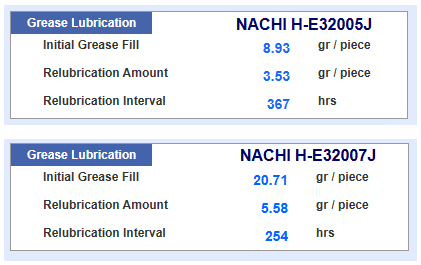
The spindle bearings should be greased with Kluber Isoflex NBU-15 spindle bearing grease for best results and longest life span. The grease amounts for each bearing are listed in grams for each bearing as follows. It is easiest to measure using a syringe with cubic centimeter graduation. Kluber isoflex NBU-15 has a weight of 0.99 grams per CC so you can safely use cc’s for the below volumes represented in grams. Fill the syringe to the appropriate volume for each bearing and spread the grease thoroughly around the rolling elements of the bearings.
💡 Note: If you intend on running the mill for extended periods of time at max rpm, you can reduce the volume of grease used by 20% to avoid any heat build up from pushing excess grease around. Note that if you do reduce the initial fill, you should cut your greasing interval by 50% to ensure the bearing are never run dry.
Bearing grease quantities per Nachi:
Initial spindle running and belt tensioning
During initial startup of the spindle, you will take the time to set a few things up, the first is the belt tension. The 4 M8 flange nuts hold the motor in place and must be just loosened enough to allow the motor and plate to slide. Start the spindle running at about 500 rpm and allow to run under light tension for a few minutes to warm the belt up. After about 5 minutes of running, add tension to the belt. I do this while the motor is running and the spindle under free load. I slide the plate backwards towards the column until the slack is visibly take up in the belt while running. This will make more sense in practice then in reading as you will be able to see the change in the belts behavior. Only tighten the belt with as much force as you can apply by pushing back with your hand. While holding it in tension tighten the nuts on the side you have access too, then tighten the other side as well. This adjustment is fine for break in, we will revisit this again once the bearings are fully broken in and will repeat the process while at max rpm to adjust for the minimum amount of vibration. When properly set the headstock should feel silky smooth at max rpm which will contribute to excellent surface finishes on your parts and best dimensional tolerance outcomes.
At this point you are ready to begin the break-in procedure below. During break in procedure when you have the motor up around the 2000rpm point, you will adjust the preload on the set screws holding the spindle cartridge in place. Here is where you will notice the difference in sound the spindle makes while running when the set screws are too tight verses just right. Start with the screws just tight enough to retain the spindle in the head casting, an extremely light preload. While running slowly tighten each one until you notice a change in sound, then back off until the sound returns to the initial loose state, this will be the correct preload with minimal deformation of the spindle housing. This will ensure the best bearing bedding in and least amount of runout in your spindle. Do this for each set screw.
Overview: Very important, during break in, NEVER stop the spindle while hot. Always run the spindle down to ambient temperature before stopping.
During break in do not allow the spindle temperature to go above 150F. The use of a infrared temperature gun is recommended. When sighting the spindle, aim near top of the spindle cartridge just below the bottom of the head casting. This will give a good reading. Be aware that time for heat soak will yield a delayed actual reading. The 150F limit accounts for this delay. While the spindle case may read 150F, the bearing and rolling elements may be nearer to the maximum service temperature.
If the spindle temps reach 150F before reaching 3000RPM, you should recheck the bearing preload as it may be too tight. Having the preload too tight can cause a runaway temperature rise as preload increases with temperature and speed. This can damage the bearings.
To start the break in, the spindle should be run in incremental steps of 500RPM for 5 minutes. You will proceed to each higher RPM step until reaching the max break-in temp limit of 150F. Below is an example, your temperature readings will be different but the procedure remains the same:
500 RPM for 5 minutes, starting temp reading: 72F Step End temp reading: 85F
1000 RPM for 5 minutes, starting temp reading: 85F Step End temp reading: 95F
1500 RPM for 5 minutes, starting temp reading: 95F Step End temp reading: 105F
2000 RPM for 5 minutes, starting temp reading: 105F Step End temp reading: 115F
2500 RPM for 5 minutes, starting temp reading: 115F Step End temp reading: 125F
3000 RPM for 5 minutes, starting temp reading: 125F Step End temp reading: 135F
3500 RPM for 5 minutes, starting temp reading: 135F Step End temp reading: 150F
Since the temp reading reached 150F, you will want to reduce spindle speed by 500RPM back down to 3000RPM and run until temperature stabilizes under 120F. If temps do not reduce or continue to climb at 3000 RPM, reduce in 500RPM increments until temperature stabilization is achieved.
From this point on there will be a lot of up and down progression and regression while the rolling elements and races bed in. Do not skip over any 500RPM increment. You may find that shorter periods at the higher RPM’s are needed and this is normal. Proceed until you can sustain 6000RPM for 1 minute without exceeding 150F and continue temp RPM cycling down to 120F and back up to 6000RPM until you have a sustained 5 minutes while below 150F.
To finish the break in, reduce spindle RPM in increments of 1000RPM for 2 minutes each step down all the way to 1000RPM. Allow to run at 1000RPM until within 10F of room temperature.
Turn off spindle and allow to cool overnight.
Monitor temps for the first few cycles on parts, they should not be nearly as hot and with a couple of heat cycles should be able to sustain 6k RPM continuous without going much above room temperature.
Always run the spindle for warm up for a few minutes, it’s good to have a warm up cycle for the machine that runs it up slowly to warm up the components before putting under load.
Step 17
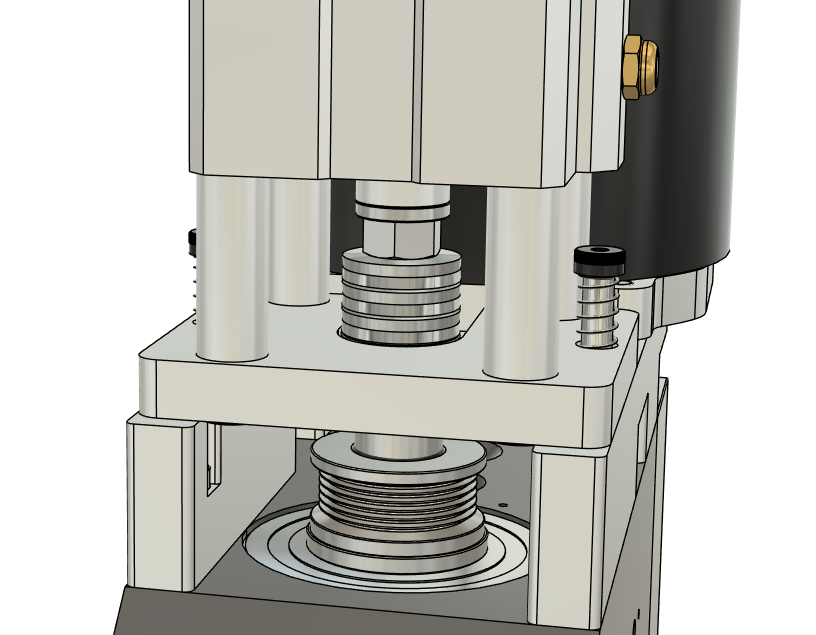
Install the drawbar assembly. In order to install the power drawbar assembly, we must install the actual Drawbar with the disc springs correctly stacked ()()() as portrayed by the parenthesis in a triple cup edge to cup edge arrangement and installed onto the drawbar. Next slide the drawbar through the tophat and into the spindle. Install the R8 TTS collet into the spindle aligning the locking key slot to the spindle alignment pin. Hand tighten the drawbar into the collet to hold it in place. Install a TTS tool holder to into the collet in the spindle. Now using your factory spindle pin wrench or similar, hold the lower spindle while tightening the top of the drawbar. You will begin compressing the disc springs as you tighten the drawbar. While tightening, periodically check to see if the air cylinder assembly will slide onto the motor stands with the piston clearing the top of the drawbar face. Once you have tightened the drawbar enough to have at least 0.010” clearance, this is a good preliminary adjustment place before we have the air operated cylinder properly connected. Now install the power drawbar air cylinder assembly by sliding it into place from the front of the machine. Install the 2 shoulder bolts with springs installed over the shoulders. These are the retentions springs that help keep the drawbar seated during machine use. The shoulder bolts are guide pins that maintain alignment with the spindle. It can be tricky getting the bolts started while under spring pressure but be careful not to cross thread the fasteners. Use fingers to start the first few threads. Once properly started, tighten both fasteners with your allen key wrench.
Step 18
Mount the air cylinder Solenoid Valve somewhere near your control cabinet where you have access to an air source. You will need to source the proper fittings for the hose supplied and it is recommended to add a manual shutoff valve pre solenoid. Once mounted route the supplied air hose from the outlet on the solenoid valve that says “To Air Cylinder” to the open hose fitting at the bottom of the air cylinder fitting side. It is recommended to use a cable drag chain or similar cable management method for housing the air line, so it never gets kinked or damaged from the z axis motion. Be sure to account for the z axis motion when sizing up where to trim the hose. Measure twice cut once and when in doubt leave it longer than you think it should be. For testing purposes, you can leave it full length and trim it later once you have installed some form of cable management and can clearly identify the best place to cut those hose.. Connect the input side of the solenoid valve to your air source. For longevity of the pneumatic components, the air used should be dry and oil free to avoid premature wear or damage to the o-rings and seals.
Step 19
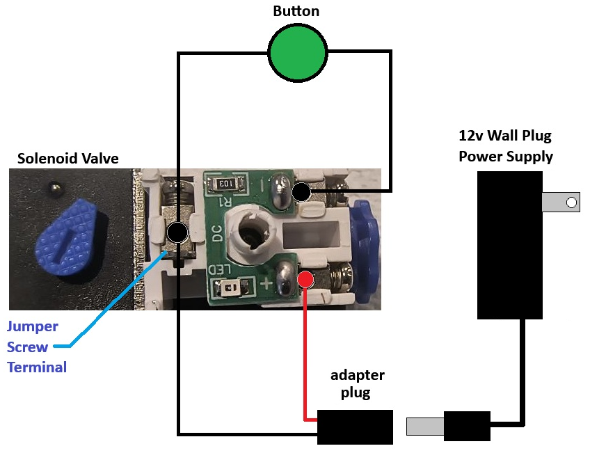
Mounting the momentary Push Button. Choose a place on the head of the machine to mount the momentary pushbutton. The most common place is the front of the head using a fabricated sheet metal plate covering the existing opening on the casting where the previous slide caliper used to be housed, but the mounting location is at you’re your own discretion. Once you have a settle upon location, route the supplied wire from the button location to the solenoid valve leaving ample extra for wiring things in and enough slack to perform any future maintenance. See the below wiring diagram for the most basic way to connect the solenoid. Use proper wiring practices per your local regulations. This diagram ONLY shows the connection points on where the components should be connected to for a basic circuit.
Step 20
Setting the drawbar preload. Now that you have the wiring installed and with the airlines connected and a pressure source nominally between 120psi and 150psi, it is time to set the drawbar preload tension of the Belville disc springs.
⚠️ Important: NEVER allow the collet to be released without a tool holder in it or damage to the spindle taper and or the collet can occur! It is NECESSARY to have a dummy holder or 3/4” plug to leave in the R8 collet in the spindle when not in use!
To begin setting the spring tension preload, there should still be a tool holder in the collet from the initial installation of the drawbar air cylinder. While holding onto the tool holder (so it doesn’t drop onto the table when released) press the release button for the drawbar. The tool should release easily. Do this a couple of times to allow everything to align and the springs to cycle a few times while under initial tension.
Scenario 1: If the tool cannot be removed from the collet while the drawbar release button is activated, check your air pressure and ensure it is in the nominal range. if air pressure is within nominal range, deactivate the draw bar button by releasing your finger from it. Now we will need to loosen the drawbar by holding the spindle with the factory pin tool or similar spindle locking tool, and loosening the top of the drawbar on the hex just above the disc springs. Make small adjustments of a ¼ turn and retest until the tool can just be slid out by hand from the collet with the drawbar release button activated.
Scenario 2: If the tool releases easily with no drag from the collet, you can make ¼ turn adjustments to the drawbar tightening it and retesting the tool release until the tool slides out of the collet with a light drag. This will be your correct drawbar tension.
Final checks: Make careful note that after the correct tension is set that there is still a gap between the top flat surface of the drawbar and the air cylinder piston and there is no contact when the air cylinder is fully retracted. These two piece MUST NOT be in contact when the spindle is running.
Step 21
Now that the kit is fully installed, you can take the time to complete final tramming on the column and head to ensure your machine is properly aligned.
Preparation
for tramming: First things first, ensure the the X, Y and Z axis gib adjustment is correct and that motion of all 3 axis is smooth and tight without play nor binding. Having these adjustment correct ensures the machine is in its proper state of affairs before we begin adjusting Items that build upon those correctly adjusted gibs.
Tram Step 3
Now that the machine is assembled and the column was previously trammed at the beginning of the document in step 2 of assembly and we have trammed for Z axis travel in relation to X and Y axis, we now need to make sure that the spindle centerline is also perpendicular to X and Y axis. In similar fashion to the column tramming steps the first for tramming the head will be to tram the front to back tilt. This will be adjusted if needed by adding shims to the top or bottom of the head between the z saddle and the head spacer. The easiest method for testing spindle tram is with a spindle tramming aide such as the one seen below. However it can be done with an indicator mounted to the spindle, it is just a bit more tedious to do. Given you will need to tram the spindle after any crash of the machine (which does happen even to the pros) I will demonstrate tramming with the proper tramming aide for representation. The process is the same for single dial test indicator, but you must record each measurement verse being able to see both at the same time and easily adjust the tram with visual feedback during adjustment. Below you can see the initial setup of the tramming aide on the table to check for front to back head tilt.
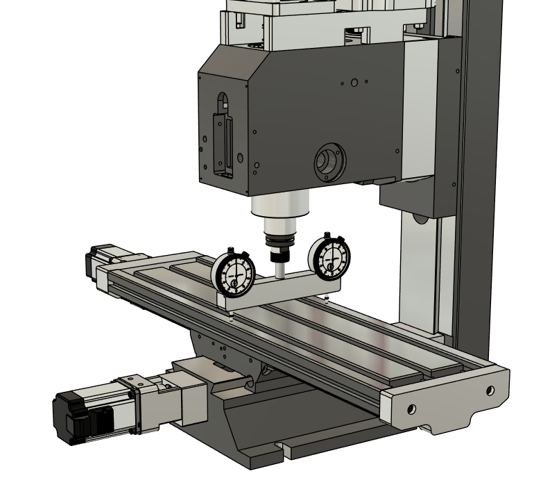
First step is to zero the indicator faces to the dials with both stems touching the table and movement of the dials verified so they will read the delta when rotated in the next step. Now rotate the spindle by hand 180 degrees and record where the dial indicators moved to. If the indicator that is now towards the rear of the machine is showing movement of the dial to the Plus side of zero, it is showing the head is tilted up towards the front of the mill by the amount shown on the indicator across the width of your tramming aide spread. In this scenario you would add a shim with thickness of half the indicator readings value between the top of the head spacer and z saddle to reduce the tilt, retighten the head assembly Then rerun the previous steps again to identify the improvement. If the dials remain at zero when rotated the head front to back tilt is now trammed, if not repeat until it is in tram, this will be where the spindle centerline is perpendicular to the Y axis. If the indicator reading was off to the negative side during the initial reading, then shimming would be added at the bottom of the head spacer and z saddle to tilt the head upwards and bring it into tram.
Tram Step 4
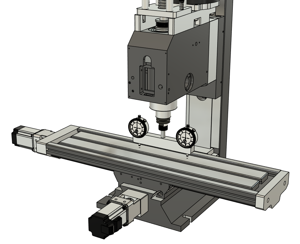
Tramming the head in the left to right rotation angle is easier as we can simply loosen the nuts holding the head assembly to the z saddle and rotate the head by gently tapping it with a deadblow until tram is achieved and retighten and test until tram has been found to show zero on both indicators in the initial position and rotated 180 position. As seen below with the tram aide parallel to the X axis:
Great you have now successfully trammed the machine for all motion axes and should be on your way to making some chips! Run through the document one more time to make sure nothing was overlooked, double check all of your hardware and mark critical fasteners with a grease pen to remind yourself they have been properly torqued down. Once complete you should be ready to put your machine back into operation. Be sure to keep track of spindle run time for bearing grease intervals and monitor spindle housing temperatures for the first few days of running to make sure the bearings are healthy. These modifications should make for a very noticeable improvement in your machines performance and speed as well as quiet, smooth and vibration free spindle. With proper tooling and a good cutting lubrication method such as mist coolant or flood coolant, your surface finishes should come out very smooth and shiny with minimal if any side wall distortion. The recommended tooling size for these mills in cnc form is 3/8” for endmills, this is a great balance of size and rigidity that will give the best cuts. Larger endmills can be run but as the diameter goes up the machine rigidity becomes more of a barrier to good surface finishes. Reducing spindle speed with larger tooling will help.
If you have any questions or need assistance with any part of the installation of the kit, please do not hesitate to reach out, I am happy to help my customers succeed with their machine builds and enjoy the reward of being a part of their journey!
Happy chip making!